???
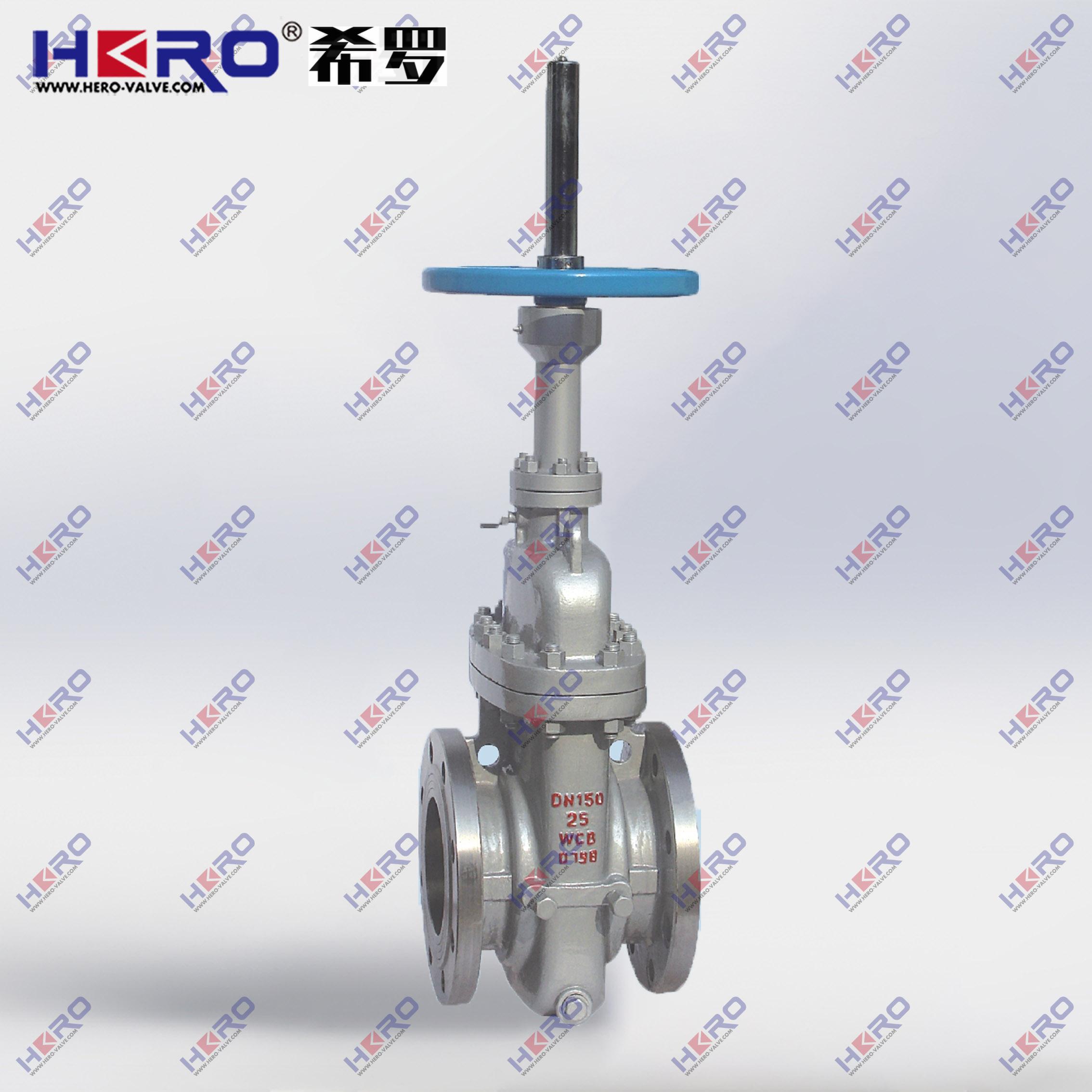
The flat gate valve is a sliding valve with parallel gates as the closing part. The closing part can be a single gate or a double gate with a spreading mechanism between them. The pressing force of the gate to the valve seat is controlled by the medium pressure acting on the floating gate or floating valve seat. If it is a double-disc flat gate valve, the spreading mechanism between the two gates can supplement this pressing force.
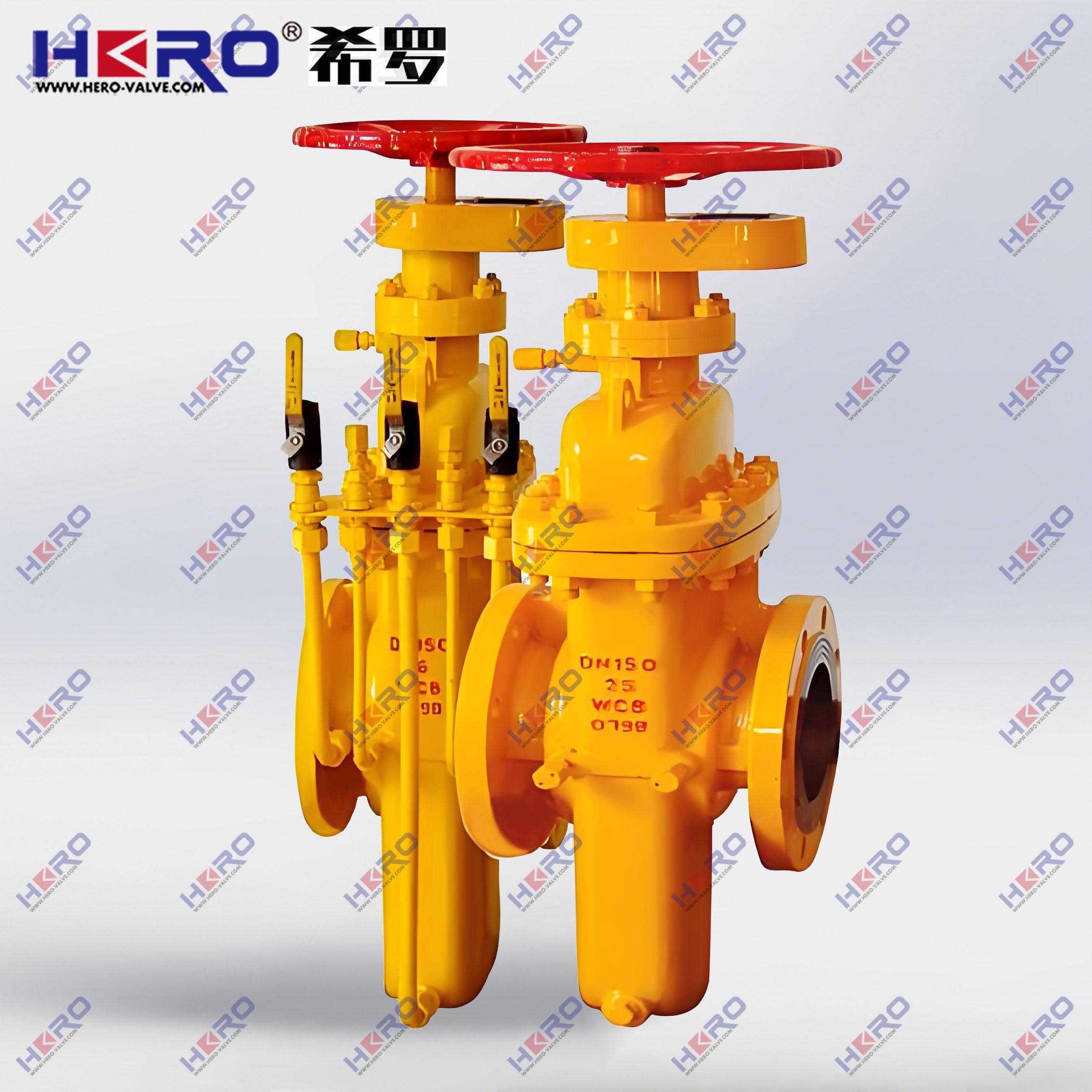
one,Structural features
This series of products adopts a new floating seal structure and is suitable for use on oil and natural gas pipelines with a pressure not exceeding 15.0MPa and a temperature of -29 to 121°C as a start-stop and regulating device for controlling the medium. The product has a novel structural design, appropriate material selection, strict testing, and easy operation. It has strong corrosion resistance, wear resistance, and erosion resistance, and is an ideal new type of equipment in the petroleum industry.According to the driving mode, the flat gate valve can be divided into manual flat gate valve, pneumatic flat gate valve and electric flat gate valve. According to the purpose and application, it can be divided into flat gate valve with diversion hole, flat gate valve without diversion hole, oilfield flat gate valve, pipeline flat gate valve and gas flat gate valve.
2. Working Principle
1. Adopt floating valve seat, two-way opening and closing, reliable sealing, flexible opening and closing.
2. The gate plates are all equipped with guide strips to provide precise guidance, and the sealing surfaces are all spray-welded with hard alloy to resist erosion.
3. The valve body has high load-bearing capacity and the passage is straight-through. When fully opened, it is connected with the gate guide hole and is similar to a straight pipe, with very small flow resistance. The valve stem adopts composite packing and multiple seals, which makes the seal reliable and has low friction.
4. When closing the valve, turn the hand wheel clockwise, the gate moves down to the bottom, and due to the medium pressure, the inlet sealing seat is pushed toward the gate, forming a larger sealing pressure ratio, thus forming the first seal. At the same time, the gate is pressed against the outlet sealing seat, forming a double seal.
5. Due to the double seal, the wearing parts can be replaced without affecting the operation of the pipeline. This is an important feature that makes our products superior to similar products at home and abroad.
6. When opening the gate, rotate the hand wheel counterclockwise, the gate moves up, and the guide hole and the channel hole are connected. As the gate rises, the through hole gradually increases, and when it reaches the limit position, the guide hole and the channel hole coincide, and it is fully open.
3. Performance Specifications
Nominal pressure | 1.0 | 1.6 | 2.5 | 4.0 | 6.4 | 10.0 |
Nominal diameter | DN25~DN900 |
Working pressure (MPa) | ≤1.0 | ≤1.6 | ≤2.5 | ≤4.0 | ≤6.4 | ≤10.0 |
Strength test (MPa) | 2.0 | 2.4 | 3.75 | 6.0 | 9.6 | 15.0 |
Sealing test (MPa) | 1.1 | 1.76 | 2.75 | 4.4 | 7.1 | 11.0 |
Working medium | Water, oil, natural gas, etc. |
Working temperature | -29~121℃ |
4. Use, maintenance, care and precautions
1. The valves are subjected to strength and sealing tests before leaving the factory. All joints should be kept in their original state during use.
2. The operating handwheel of this series of valves is marked with the opening and closing rotation direction mark, and the upper part of the rising stem type is equipped with an opening and closing height scale for adjustment indication.
3. When welding this valve to the pipeline, the valve should be opened and the neck should be properly protected with moist objects to minimize high-temperature heat conduction to prevent damage to the sealing packing.
4. It is strictly forbidden to use the force rod when closing the valve. When the gate is closed to the top, the handwheel should be turned 1/2 turn to make the gate in a floating state.
5. When the valve is in use, a certain amount of grease should be regularly injected into the grease injection joint of the valve cap.
6. If the valve leaks due to wearing parts during use, it should be replaced in time.
7. During the inspection and maintenance of the valve, the inner cavity should be cleaned and grease should be added to each transmission part during assembly.
8. When the valve is not in use during storage, the gate should be in the closed position. For long-term storage, it should be placed in a ventilated and dry place and inspected and maintained regularly.
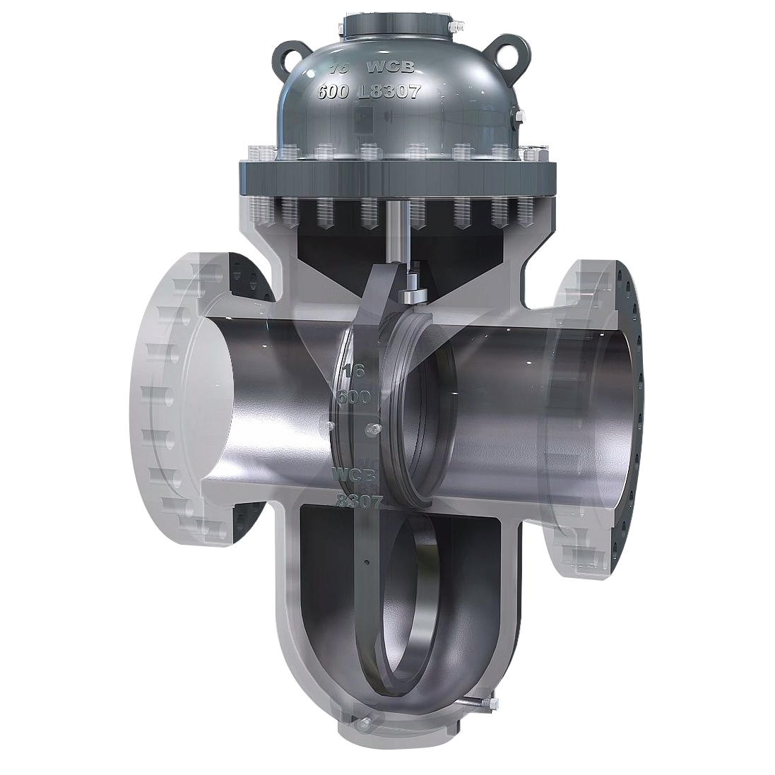
Internal structure
1. The valve seat adopts O-ring sealing and floating valve seat structure with pre-tightening force, so that the inlet and outlet of the flat gate valve are sealed in both directions; and the opening and closing torque of this structure is only 1/2 of that of ordinary valves, which can achieve easy opening and closing of the valve.
2. When fully opened, the channel is smooth and straight, the flow resistance coefficient is extremely small, there is no pressure loss, and the pipeline can be cleaned by hair balls
3. The self-sealing packing structure has more reliable sealing than ordinary graphite packing, and grease is injected into the packing sealing surface, so the sealing surface reaches the zero leakage standard, which solves the common problems of running, dripping and leakage of general valves.
4. When the flat gate valve is closed, it can automatically release the high pressure in the inner cavity to ensure safe use
5. Fully enclosed structure, good protection performance, can adapt to all-weather requirements
6. The valve seat sealing structure should be elastic and pre-tightened, and the upstream and downstream sealing seats should be sealed at the same time. The valve seat and the seal should always be face-to-face sealed.
7. The valve seat has a self-cleaning function and is not directly washed by the air flow during the opening or closing of the valve. The valve seat should be made of lubricating and non-wearing materials.
8. Failure of the valve actuator will not affect other parts of the valve, and maintenance and replacement work can be carried out without removing the valve.
9. Yoke Bushing – Aluminum bronze yoke bushing is equipped with needle thrust bearing to minimize operating torque.
10. Stem – Threaded length to bracket; pinned and spot welded; for stability.
11. Pressure Seal – Simple construction with segmented retaining ring and silver plated mild steel gasket to facilitate disassembly and achieve the best bonnet seal.
12. Seat Ring – The welded seat ring is perpendicular to the flow path for easy maintenance.
13. Actuator – These valves can be equipped with electric, hydraulic or pneumatic actuators. Standard manual handwheels are available for valves below DN300 and helical gear operators are available for valves above DN350.
14. Yoke – The fully assembled yoke is seismic tested and easy to maintain and install the actuator.
15. Gland – Two-piece, self-adjusting gland to avoid ejection.
16. Integral rear seat – hard surface for longest service life.
17. Disc – The spring loaded disc is self-adjusting, reducing the torque requirement on the actuator.
18. Integral stop – Integrally cast bracket stop device positions the assembled bracket disc, making the valve seat more stable and reliable.
19. The valve body has two structures: casting and welding.
20. The valve seat adopts an O-ring seal and a floating valve seat structure with pre-tightening force, which makes the valve inlet and outlet sealed in both directions; and the opening and closing torque of this structure is only 1/2 of that of an ordinary valve, which can easily open and close the valve.
21. For metal-to-metal sealed valves, a grease injection structure is provided on the outside of the valve body. The grease enters the valve sealing surface through the grease injector and the valve seat, making the valve achieve zero leakage.
22. The valve seat is inlaid with PTFE on the sealing surface, which has double sealing of PTFE to metal and metal to metal. The PTFE sealing surface also has the function of removing dirt from the gate.
23. The gate and valve seat are treated with special technology, spray-welded with hard alloy and wear-resistant PTFE to achieve double sealing. Grease can be injected to assist the double protection of sealing, making the sealing more reliable and the service life longer.
24. The gate of the valve with diversion hole always matches the sealing surface whether it is fully open or fully closed, and the sealing surface is protected from direct erosion by the medium, thereby extending its service life.
25. When the valve is fully opened, the passage is smooth and straight, the flow resistance coefficient is extremely small, there is no pressure loss, and the pipeline can be cleaned with hair balls.
26. This valve adopts a packing structure with self-sealing ability, which does not require frequent adjustment, is extremely easy to open and close, and has reliable sealing performance. The stuffing box is equipped with an auxiliary sealing grease injection structure, and the sealing performance is absolutely reliable, truly achieving zero leakage; it solves the problem that the packing of general valves is most likely to leak.
27. When the valve is closed, it can automatically release the high pressure in the inner cavity to ensure safe use.
28. Fully enclosed structure, good protection performance, can meet all-weather requirements.
29. The valve is equipped with an indicator rod or observation window to show the opening and closing status of the valve.
advantage
The flow resistance is small. The flow resistance of the non-shrinking port is similar to that of a short pipe. The flat gate valve with a diversion hole can be directly cleaned with a pipe cleaner when installed on the pipeline. Since the gate slides on the two valve seat surfaces, the flat gate valve can be used for media with suspended particles. The sealing surface of the flat gate valve is actually automatically positioned. The valve seat sealing surface will not be damaged by the thermal deformation of the valve body. Moreover, even if the valve is closed in a cold state, the thermal elongation of the valve stem will not overload the sealing surface. At the same time, when the valve is closed, the flat gate valve without a diversion hole does not require a high precision in the closing position of the gate, so the electric flat valve can use the stroke to control the opening and closing position.
Selection principles
1. For oil and natural gas pipelines, use single-disc or double-disc flat gate valves. If the pipeline needs to be cleaned, use single-disc or double-disc rising-stem flat gate valves with diversion holes.
2. For the transportation pipelines and storage equipment of refined oil, use flat gate valves with single or double gates without diversion holes.
3. For wellhead devices for the extraction of oil and natural gas, single or double disc flat gate valves with concealed stem floating valve seats and guide holes are selected. Most of them are API16A standards, and the pressure levels are API2000, API3000, API5000, API10000, API15000, and API20000.
4. For pipelines with suspended particle media, knife-type flat gate valves should be used.
5. For city gas transmission pipelines, use single-disc or double-disc soft-sealed rising-stem flat gate valves.
6. For urban tap water projects, choose single-disc or double-disc open-stem flat gate valves without diversion holes.
Common specifications
Specification range | DN25~DN900 |
Temperature range | -29~121℃ (High temperature type needs to be customized) |
Pressure Range | Pressure range: 16 bar ~ 100 bar |
Valve body material | WCB/304/316/WC6/WC9 |
Stem material | F6A/F304/F316/F304/F304 |
Valve cover material | Same as the main body |
Valve plate material | Stainless steel/alloy steel |
Connection | Flange |
Scope of application | Water, oil, gas, fuel gas and some corrosive liquids |