Control Mechanism: An internal feedback control mechanism is composed of a valve stem connection component and a plug. The pressure feedback mechanism is set at the front of the valve.
Other Components: It mainly consists of parts such as the valve body, valve cover, compression spring, diaphragm, stirrup - shaped fixture, valve disc, adjusting screw, and spring seat. The lower part of the valve stem is connected to the guide seal seat through a front bolt, and the upper part is connected to the diaphragm and diaphragm pressure plate through a rear bolt. The spring is pressed against the diaphragm pressure plate.
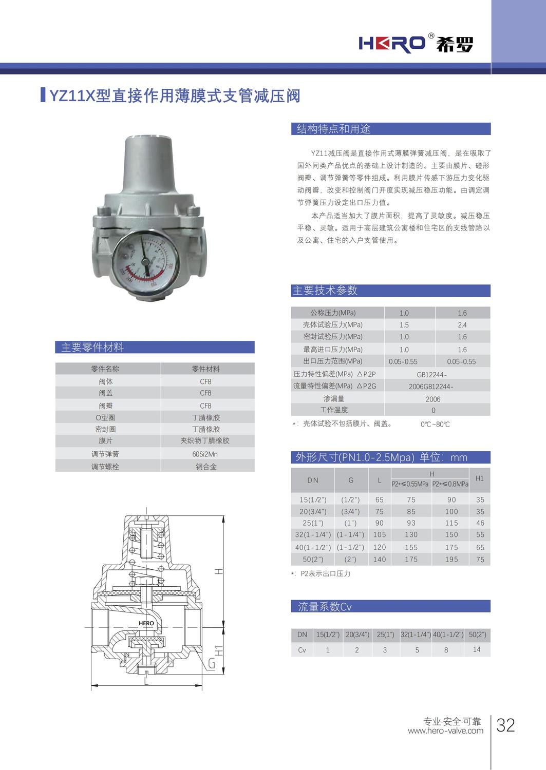
Working Principle
The outlet pressure acts on the bottom surface of the diaphragm and the bottom surface of the valve disc. When it exceeds the set value of the spring, the spring is compressed, causing the valve disc to close. As long as there is no water flowing downstream, the outlet pressure will basically remain at the set value, and its variation is only 8% of the variation in the inlet pressure. When water is used downstream, the outlet pressure drops, and the spring pushes the diaphragm to open the pressure - reducing valve. After the water flows continuously for a while, the opening of the pressure - reducing valve generates a self - damping effect, making the opening and closing actions tend to be stable.
Product Features
Simple and Reliable Structure: It adopts a direct - acting diaphragm - type structure. The internal structure is simple, free from jamming, reliable in performance, and durable.
Dirt - resistant and Easy to Maintain: It is dirt - resistant and scale - proof. There is no need to install an additional filter or a bypass pipe. The piping is simple, which can save a large amount of space and piping costs.
Precise Pressure Regulation: The outlet pressure is precisely adjustable. Under normal circumstances, the outlet pressure is basically not affected by the inlet pressure, and the variation in the outlet pressure is only 8% of the variation in the inlet pressure.
Good Hydraulic Characteristics: The pressure loss is small, and the pressure - reduction ratio can reach more than 10:1. It can meet various pressure - reduction requirements and is especially suitable for branch - pipe pressure - reducing systems.
Technical Parameters
Nominal Diameter: DN15 - DN50.
Nominal Pressure: PN6 - PN25.
Applicable Temperature: Usually - 29°C - 425°C. Some may be different, for example, some have an applicable temperature of ≤80°C.
Applicable Media: Steam, oil products, water, etc.
Outlet Pressure: Generally adjustable between 0.05MPa - 0.55MPa.
Application Scope
It is mainly used in various building water supply systems, fire - fighting systems, central air - conditioning systems, heating systems, etc. It can make the distribution of water supply pressure more balanced, avoid over - pressure in some water supply areas, optimize the water supply zoning of high - rise buildings, replace the zoned frequency - modulated variable - speed water pumps. In the fire - fighting water supply system, it can replace the zoned water pumps. In the domestic water supply system, it can protect all faucets and other water appliances.
Installation Precautions
It can usually be installed vertically or horizontally on the pipeline, but the location should be convenient for maintenance. Pay attention that the water flow direction should be consistent with the arrow shown on the valve body.
Before installation, carefully check whether the usage conditions are in line with the provisions on the nameplate.
In the domestic water supply system, the pressure - reducing valve is usually installed behind the water meter to protect all the water appliances downstream. If there is a risk of freezing, protective measures should be taken.